

Technology andSupport
SERVICE
PV-15T11C Product Manual
Release time:
2023-08-10 13:33
Source:
PV-15T11C Product Manual
Thank you for your choose our solar PV junction box. To enable you can use of this product correct, fast and safe, please read this manual before using.
Product structure and size
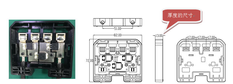
Technical parameters
Suit for: 200~400W
maximum working voltage: 100V
Rated impulse voltage: 12000/16000V DC
Rated Voltage: 1500V
contact resistance: ≤0.5mΩ
Rated Current: 15A
reverse current: 30A
Safety Class: Class II
Wire Size Range: 4mm2
Ambient Temperature Range: -40℃~+85℃
Protection Degree: IP68
Flame Resistance: UL94-V0
Install Caution
In the formal installation, you should confirm the solar module is not in working condition. If must be installed under the sunlight, please use the sun shade cover the solar module, in order to avoid its working, cause electric shock. Worker cannot contact the positive pole and negative pole at the same time, so as to avoid electric shock
The junction box cover is open before using, the connection after the junction box to ensure that good sealing
The positive pole and negative pole for terminal and the cable is clearly defined, and the user should not change or make them reverse, which may cause serious consequences.
For system maintenance, please make sure that the system is stopped working;
Do not force or the weight of junction box, connector and cable, the cable tension is less than 400N;
Recommend the use of de ethanol and acetone silica removal; if the use of oxime type silica removal, in the process of production and storage must be completely evaporate silica gel of 2-butanone oxime, otherwise it may cause plastic parts cracking and metal parts are corrosion and other undesirable phenomena.
Installation and usage
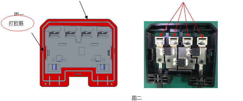

1 as shown in the red area is the silica gel coating area, the way is to apply the adhesive tape along the gel, to be the bottom of the box to be pressed into the back of the box.
2 bus from the bottom of the bottom of the box from looking down on the threading hole passes through the connection plate, and the handle of the electric iron bars soldered.
3 in Figure three shows that the filling in the order of the glue, the glue surface and the level of the level, the actual amount of plastic 30ML
4 after the need to fill the bottom of the box is placed in a cool place to wait for the glue to solidify, to be solidified before the cover can be covered. The upper cover is in the order of 1-2-3. is
The top (1) of the bottom box is deducted, and then the bottom (2) of the bottom of the box is a snap, and then buckle into the left and right (3).
Previous Page
Next Page
Previous Page
Next Page